
Container Plug BRY430P7W 480 V 3 Ph 30 Amp
Wiring Color Codes:
- Phase (Black) 208-230 V
- Phase (Red) 208-230 V
- Phase (White) 208-230 V
- Ground (Green)
NO NEUTRAL! 3 Phase WYE Only!
Delivery Zip Code
A 20ft used certified refrigerated shipping container — also called a 20-foot reefer or refrigerated cargo container — is a pre-owned, temperature-controlled steel unit you own outright, built for dependable cold storage in a compact footprint. Ideal for food distribution, pharmaceuticals, agriculture, and manufacturing where certified refrigeration matters.
What does certified mean on a used reefer? Each unit is inspected to cargo-worthy structural standards and receives a full pre-trip inspection so the refrigeration machinery is operational before delivery. Built from corrosion-resistant Corten steel with commercial-grade refrigeration equipment, a used certified refrigerated container delivers cold-chain performance without the cost of a factory-new unit.
Trusted refrigeration brands including Thermo King, Carrier, or Daikin may be installed depending on your temperature range needs. An optional dual voltage transformer allows operation in 230V single-phase environments where 3-phase power is unavailable. Perfect for catering prep, floral cold rooms, beverage staging, produce holding, and on-site pharma storage. Units ship in stock for nationwide delivery, giving you secure steel storage on a timeline that matches project deadlines without waiting on custom lead times.
Best when no unloading equipment is available. The driver backs into position, tilts the trailer, and slides the container directly onto the ground.

Best when a forklift or crane is available on-site. The container must be lifted off the trailer using a forklift rated for at least 15,000 lb or an appropriate crane. Conexwest can help coordinate additional placement equipment when needed.

Please make sure the delivery site has:
Containers can usually be placed directly on a solid, level surface without a foundation. Let us know in advance if the site is wet, muddy, soft, sloped, or difficult to access.
| Feature | Details |
|---|---|
| Exterior Dimensions | 20’ L x 8’ W x 8’6” H |
| Interior Dimensions | Approx. 18’6” L x 7’6” W x 7’5” H |
| Cubic Capacity | Approx. 1,050 cu. ft. |
| Construction | Used cargo-worthy ISO-grade steel |
| Insulation | 3" high-efficiency insulation |
| Flooring | Aluminum T-bar floor |
| Lighting | LED lighting (optional upgrade) |
| Doors | Dual cargo doors with heavy-duty weather seals |
| Power Requirements | 460V 3-Phase, 32–40 Amp typical |
| Thermo King | -40°F to +70°F |
| Carrier | -20°F to +70°F |
| Daikin | -20°F to +70°F |
Wiring Color Codes:
NO NEUTRAL! 3 Phase WYE Only!
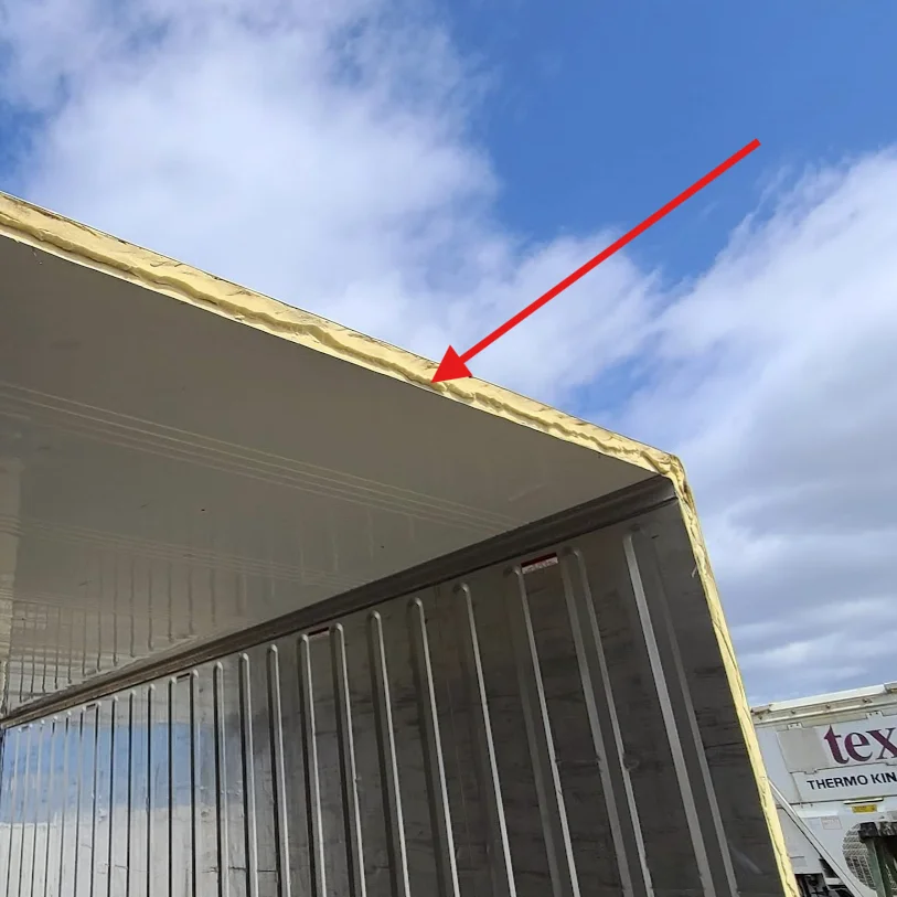
Fully insulated with 3” foam to maintain a constant internal temperature. Covers, walls, ceiling and floor.
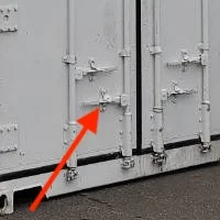
The secure closing cargo doors provide a tight and protective seal. Fit with locking rods that engage at multiple points of contact along the top and bottom of the container.

All storage containers for rent come standard with corner castings. They allow for stacking; lifting with a crane; and absorb the weight of the container.

Strengthened thermal treated aluminum floor. Withstands abrasion from foot traffic, equipment and repeated use. Keeps the contents of the container elevated so that cold air can flow underneath.

Conveniently placed for mobility around the job site. Can be moved with a 15,000 lbs forklift.
Container Plug BRY430P7W 480 V 3 Ph 30 Amp
3” Insulated Walls
Secure Closing Cargo Doors with Locking Rods
Corner Castings
Aluminum T-grade Floor
Two-way Forklift Pockets
Container Warranty
The container shell is covered by a 5-year limited warranty against structural defects and corrosion.
Refrigeration Machinery Warranty
The used refrigeration machinery comes with a 6-month limited warranty covering operational components at the time of delivery.
Warranty Details
Routine maintenance, consumable parts, and damages caused by misuse, external events, or lack of care are not covered.
Optional extended warranty plans are available upon request.
For full warranty terms and conditions, click here.


Motor Evaporator Fan Assembly
$250

Motor Evaporator Fan
$450

Rent 20ft Refrigerated Container
$799/Month
4 weeks billing cycle

40ft Refrigerated Container
$7,995

20ft Blast Freezer Container-40°F to 70°F
$61,450

Single-Phase 20ft Temperature Controlled Storage Low Temp
$16,500

Single-Phase 20ft Temperature Controlled Storage Medium Temp
$16,500

10ft Refurbished Refrigerated Shipping Container
$14,250

20ft Shipping Container
$1,325

10ft Ground Level Office Container for Sale
$10,969